
WHITE TRASH NETWORKS / AMERICAN IRON TECHNICAL ARCHIVE / UPDATED NOVEMBER 2026
MILWAUKEE-EIGHT — FOUR-VALVE DESIGN, OILING, CAMS AND WORKSHOP DIAGNOSTICS.
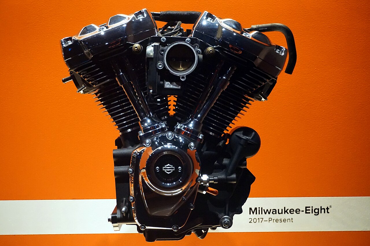
The Milwaukee-Eight brought Harley-Davidson’s Big Twin into a four-valve, dual-plug-per-cylinder architecture with a single chain-driven camshaft and modern electronic engine management. Introduced on 2017 Touring models and expanded to the redesigned 2018 Softail family, it now spans multiple displacements, cooling strategies and variable-valve-timing configurations. This technical library separates the real hardware from generic M8 marketing and lays out a disciplined diagnostic and upgrade process.
Written as an independent researched workshop reference for experienced owners and technicians. It is not a factory service manual and does not claim teardown, dyno or parts testing by WTN. For any torque, engine clearance, wear limit, electrical value, lubrication quantity or adjustment, use the correct factory service publication and manufacturer part number for the exact VIN and engine version.
MECHANIC’S STARTING RULE
Begin with the frame VIN, exact model year, engine stamping, engine family, displacement, cooling, factory ECU configuration and documented modifications. A cylinder’s exterior profile does not prove an engine is original to the frame. Check current TSBs, recalls, service manual revisions, replacement part supersessions and service history before planning a repair.
An original 2017 Touring M8 107, a 2018 Softail M8 114 and a recent CVO 121 VVT are not interchangeable just because their engine covers look related. The correct calibration, engine oil-check stance, cooling, cam drive and replacement components depend on year, model and VIN.
VERSION & FITMENT CONTROL
Identify the engine before choosing parts
| M8 generation / application | What differs | Confirm before service |
|---|---|---|
| 2017 Touring / CVO / Trike | Initial 107/114 M8 production; oil- or liquid-cooled cylinder-head configurations; rubber-mounted touring powertrain | Touring VIN, 107/114, head cooling, oil pump part number, ECM configuration |
| 2018+ Softail | M8 transition to redesigned Softail chassis; different balancer and mounting application from Touring | Softail-specific case, oiling, mounts, electrical harness, chassis oil-check method |
| Subsequent Touring / Softail 107, 114, 117 | Displacement, cooling, heads, throttle-body and calibration evolve by model-year and market | Exact engine, emission/calibration family, parts index and supersession |
| 2023+ selected CVO / 121 VVT applications | VVT hardware and liquid-cooled heads on designated models; some newer high-output engines are non-VVT | VVT yes/no by VIN, cam and oil-system pieces, coolant circuit, ECM security and calibration |
| Stage kits, 128/131/135 etc. | Aftermarket or H-D kit builds vary by compliance region, heads, pistons, oil pump and cam | Complete kit number, included hardware, explicit compatibility and applicable emissions rules |
WORKSHOP CHAPTER 01
Architecture — eight valves, two spark plugs per cylinder
Each cylinder carries four valves operated by pushrods and rocker gear, rather than the two-valve-per-cylinder Twin Cam design. Two spark plugs serve each cylinder. The M8 uses a single camshaft driven by chain and a 45-degree V-twin crank layout. It preserves Harley’s external V-twin character while substantially changing head flow, combustion, oil cooling and electronics.
Do not read a single published horsepower value as an across-the-family specification. Engine variants differ in chamber, compression, porting, exhaust, intake, gearing and calibration. Define the actual engine before making a theoretical power calculation.
WORKSHOP CHAPTER 02
Cooling — air/oil, Twin-Cooled and newer centre-cooled variants
Not all M8 cylinder heads reject heat the same way. Initial Touring models include oil-cooled and Twin-Cooled liquid-head configurations; more recent CVO engines use updated head cooling architecture. A liquid-cooled cylinder-head system is not equivalent to a fully liquid-cooled engine block. Follow the plumbing and identify radiators, pump, temperature sensors and coolant services on the specific bike.
For overheating, check ambient and load conditions, oil level with proper hot-check stance, fan/radiator function where equipped, coolant condition, inlet air leaks, fuel and ignition calibration, exhaust restrictions and correct temperature sensor signals. Do not automatically blame a hot exhaust cover for actual engine overheating.
WORKSHOP CHAPTER 03
Oil system — dry sump, crankcase scavenging and oil-check stance
The Milwaukee-Eight uses pressurized dry-sump lubrication. Oil level measurement can depend on year, chassis and whether the motorcycle is upright or on the jiffy stand. Harley-Davidson published an updated 2026 oil-check quick-reference guide to prevent incorrect level interpretation. An apparent low level after running is not proof of an external leak; verify test conditions and allow the specified return process.
When investigating suspected sumping, log oil level before/after under comparable conditions, oil-pressure readings where indicated, return/scavenge health, pump condition and venting. Do not substitute an aftermarket pump for checking crankshaft runout, sealing, pressure and the reason for excess oil accumulation. A fresh cam installation should include pump, plate and tensioner compatibility checks.
WORKSHOP CHAPTER 04
Camshaft, cam plate, lifters and valve-train geometry
The M8 has one chain-driven cam, not a Twin Cam two-shaft setup. Before selecting a cam, record displacement, compression, cylinder head version, VVT or non-VVT design, intake, exhaust, ECU generation, permitted emissions configuration and actual load. Lift, closing timing and lobe separation must be matched to spring and piston clearances, not purchased on peak-power advertising alone.
Inspect tappets, guides, pushrod length, rocker operation, timing components, valve springs, cam bearings and the pump/plate interface according to the selected kit instructions. Certain factory Stage 2 sheets specify separate oil-pump assemblies for 2017–2019 applications, plus cam retention hardware. Treat kit instructions as the compatibility authority and verify newer superseded parts.
WORKSHOP CHAPTER 05
Crankshaft runout and oil-pump alignment
Measure runout using the instrument position prescribed by the selected manufacturer procedure. Excess runout can make cam gear-drive choices risky and can influence oil-pump alignment and wear. Publish both the numerical TIR and the method, not a casual statement that a shaft is ‘true’.
The permitted values depend on the operation, assembly and kit. A measurement suitable for a particular H-D service step may not satisfy a separate aftermarket kit. Do not mix generic forum limits with workshop data or conflate acceptable engine operation with gear-drive eligibility.
WORKSHOP CHAPTER 06
Variable valve timing — 121 VVT and related variants
VVT-equipped Milwaukee-Eights change valve event timing dynamically and involve mechanical timing hardware plus specific ECM control. A VVT 121 should not be treated as an ordinary fixed-cam 117 or 121, nor should the VVT system be deleted as a casual cam upgrade. Some official performance packages explicitly remove factory VVT for a particular application; that change has major calibration and compliance consequences.
For complaints involving transient torque, engine light or phaser control, begin with VIN-specific factory diagnostics, oil-system health, sensor information and exact fault codes. Do not remove a phaser or command actuators without an appropriate service procedure and suitable diagnostic equipment.
WORKSHOP CHAPTER 07
Fuel injection, ride-by-wire and ECU calibration
Electronic throttle control, oxygen-sensor strategy, knock input, intake air temperature, engine temperature, manifold pressure and model-specific throttle bodies all matter when an engine is modified. On a production machine, record DTCs and adaptation data before clearing or flashing. Save the baseline calibration if permitted, verify electronic throttle response and confirm fuel pressure, injector identity, intake sealing and harness condition.
Cam and air-filter changes can move the volumetric efficiency map. Dyno verification should include hot restart, idle quality, tip-in, cruise, full-load fueling and repeatability, not just a peak-pull number. A map created for a 2017 107 must not be applied blindly to a 2024 CVO VVT or to an engine with different heads.
WORKSHOP CHAPTER 08
Compression, leak-down and top-end sealing
Evaluate cylinder condition before any high-compression or big-bore build. Compare compression values under consistent starting conditions, then locate leak-down paths at the exhaust, intake, crankcase and head interface. Check ring end gap, cylinder taper and bore, piston-to-wall clearance, head sealing, valves and guides using factory and component-maker procedures.
Aftermarket piston, gasket and head combinations can change effective compression and squish clearance dramatically. Document actual chamber volume, deck and gasket measurement rather than trusting a boxed kit’s nominal number. Repeat hot validation for thermal expansion and oil consumption concerns.
WORKSHOP CHAPTER 09
Ignition and charging — plugs, coils, harness and battery
Eight spark-plug electrodes across four plugs can create more potential sources of a misfire complaint than a traditional two-plug Twin Cam. Inspect plug type/gap only to the applicable service publication, wires/boots, coil contacts, grounds, charging and battery. The ECU manages ignition timing on modern M8s; an aftermarket coil does not independently create more commanded timing.
Misfire diagnosis should correlate engine speed, cylinder, heat, load, DTCs and coil/plug condition. A low battery or charging fault can produce cascading sensor errors. Photograph any connector corrosion before cleaning to document water entry or damaged terminals.
WORKSHOP CHAPTER 10
Primary, clutch, compensator and driveline
Many complaints described as engine knocking, shudder or poor throttle response begin in the primary, clutch, compensator, mounts or wheel/tire assembly. Inspect the clutch’s actuation and clutch pack, primary drive and final drive before opening an otherwise healthy engine. A torque increase can expose marginal friction capacity or alignment problems.
Transmission parts and shift-drum revisions are model-year-specific: Harley technical bulletins document 2017–2024 M8 shift-drum/bearing-door compatibility changes. This is a strong example of why a parts-counter cross-reference and updated service bulletin can matter more than the owner’s description ‘it is an M8’.
WORKSHOP CHAPTER 11
Heat management and tuning a loaded touring motorcycle
On a two-up Touring machine, develop torque in the rpm range actually used on steep highway grades. Check fuel quality, air cleaner, catalyst and exhaust, heat shields, charging loads, primary/clutch and load capacity. The goal is stable road performance without detonation, hot-start trouble or inconsistent idle after extended traffic.
Compare baseline and finished dyno readings only under consistent correction settings, tire pressure, gearing, temperature and fueling. A 130-horsepower screenshot without the head work, compression, load and calibration is not meaningful build documentation.
WORKSHOP CHAPTER 12
High-output builds — displacement, springs, crank, clutch and warranty
A 128, 131 or 135 build can have a different approved part list depending on the bike. Confirm that the required heads, cylinder machining, pistons, rings, cam, pushrods, lifters, valve springs, oil pump, clutch, transmission loading, ECU calibration and cooling are all within a named kit’s applications. Factory warranty and emission status are separate questions from whether hardware physically fits.
Document the complete installation: cam card, bearing and crank measurements, piston-to-valve, compression, air-fuel strategy, calibration ID, dyno curve, hot oil pressure, noise and leak check, service interval. Reinspect after break-in according to the parts provider and factory service guidance.
EVIDENCE BEFORE REPLACEMENT
Symptom-to-system diagnostic matrix
| Complaint / symptom | First checks | Avoid this shortcut |
|---|---|---|
| Noisy hot engine or cam chest | Check hot pressure/level, timing drive, oil pump, lifters, rocker supports and accessory noises | Changing cams without proving where the noise originates |
| Oil ‘missing’ after operation / apparent sumping | Follow the factory oil-check stance and hot procedure, measure return/pressure, inspect breather and pump as indicated | Overfilling after an incorrect cold reading |
| Overheat in traffic or loaded climb | Verify cylinder head cooling variant, airflow/fans/pump, oil, temp sensors, AFR and engine load | Treating a warm exhaust pipe as a complete diagnosis |
| Check engine / poor tip-in after tune | Scan DTCs and freeze frame, confirm EFI sensor network, inlet sealing, calibration and electronic throttle | Clearing codes and flashing a generic 107 map |
| Unexpected vibration or clatter on throttle | Inspect compensator, primary, clutch, final drive, mounts and runout, plus wheel/tire factors | Dismantling the engine before checking driveline noise |
| VVT-specific errors | Confirm VVT-equipped model, phaser and oil controls, DTC test plan and factory procedure | Installing a non-VVT cam or disabling controls by assumption |
| New big-bore build consumes oil | Review break-in, hot oil-check method, ring/cylinder seal and breathing, pump return, heat, leak-down | Assuming forged pistons must consume oil indefinitely |
INSPECT / DOCUMENT / VERIFY
Mechanic’s baseline inspection sequence
- VIN + revisions: confirm M8 generation, displacement, cooling, VVT status, ECM, chassis and current parts/technical bulletins.
- Diagnostic snapshot: store DTCs, freeze frame, ECU map, fuel corrections, battery/charging, cylinder balance/misfire data where available.
- Hot oil level: use the exact 2026 factory oil-check stance reference for the model; record the conditions and any prior refill amounts.
- Mechanical baseline: document compression/leak-down, plug color/condition, inlet sealing, coolant check if equipped and external oil traces.
- Cam and pump: verify chain/tensioner, pump part number and oil supply/return condition before selecting upgrade hardware.
- Measure before modifying: log shaft runout, spring requirements, chamber volume, piston-to-valve clearance and lifter/rocker configuration for the proposed combination.
- Calibration: identify throttle-body/injector/O2 strategy and ECM security; retain a permitted stock backup and check calibration support.
- Finish and validate: cold start, hot restart, loaded road behavior, knock/AFR, return oil, coolant/fans, clutch slip and dyno curve under comparable conditions.
PERFORMANCE WITHOUT GUESSWORK
Build planning and validation
- Design around a job: daily touring, towing nothing, two-up grades, hot climate, low-rpm grunt, high-rpm competition or showroom reliability are different projects.
- Choose exact fitment: 107 versus 114/117/121, Touring versus Softail, 2017–2019 pump differences, VVT versus non-VVT, air/oil versus liquid-head cooling.
- Cam kit is a system: add springs, pushrods, lifters, bearings, oil pump/cam plate, retainers and revised calibration if needed. Use the current kit service sheet.
- Brakes and suspension count: horsepower without tires, brake performance and safe suspension geometry is an incomplete upgrade.
- Measure everything: baseline and finished torque curve, pressures, temperatures, vibration and drivability. Do not rely on advertisements instead of tests.
- Compliance and warranty: confirm required emissions certification in the bike’s jurisdiction and who will support the build after installation.
PRINTABLE CHECKLIST
Service work-order record
SHOP RECORD — FILL IN BEFORE WORK
Customer / bike: ____________________ Frame VIN: ____________________ Engine number: ____________________
Model year / model code: ____________________ Odometer: __________ Engine displacement: __________
Cooling: __________ Fuel/ECU: __________ Previous work: ____________________
Complaint, reproduced under what conditions: ________________________________________________________________________
Baseline scan / codes / fuel trims / voltages / pressure / compression / leak-down / runout: __________________________________
Factory publication / revision: ____________________ Technical bulletin / part numbers: ____________________
As-found photos / fluid sample / wear measurements: _________________________________________________________
Repair performed: ____________________ Verification road test / date: ____________________
Record the measurement, test condition, instrument, units, and factory acceptance criterion together. Never write “in spec” without identifying which revision of which specification was used.
PRIMARY & SECONDARY SERVICE REFERENCES
Sources, manuals and limitations
- H-D Service Information Portal — Model-year service procedures, service bulletins, wiring, recalls and factory values.
- Factory 2026 M8 oil-level stance guide — Newer hot-check procedure; use the applicable row for chassis and year.
- H-D Screamin' Eagle M8 Stage 2 instructions (J06307) — Specific oil-pump and cam hardware requirements for listed kit applications.
- 2025 CVO Road Glide / M8 VVT information — Manufacturer confirmation of VVT engine and associated design.
- H-D 2026 performance product catalog — Example of build kits explicitly altering the factory VVT configuration.
- M8 shift-drum / bearing-door technical bulletin — Example of model-year part supersession and interchangeability limits.
- Biker Free Press M8 fitment research — Companion researched overview; not a substitute for factory repair data.
- M8 cam chest research — Companion discussion of pump/plate/lifter decisions and limitations.
Editorial note: manufacturer claims and service instructions are attributed to their issuers. Service data changes with production revisions. If a document conflicts with the machine’s part numbers or a newer bulletin, resolve the conflict through factory sources before beginning work. Changes to safety-critical systems should be checked by a qualified technician.
Discuss documented technical findings in WTN Forums · Back to WTN Performance Garage
WHITE TRASH NETWORKS / THE GARAGE
BUILT TO RIDE. RECORDED TO LAST.
WTN workshop files for the people keeping American iron on the road.
WTN WORKSHOP FIELD FILE / NOVEMBER 2026
MILWAUKEE-EIGHT / CAM FITMENT & TUNE EVIDENCE
Use this file alongside the engine chapters above. The following diagnostic and documentation workflows are WTN editorial guidance; published component requirements are linked by name.
Make the fitment record specific enough to order from
Record the complete model and year, engine and head identifiers, displacement, cooling arrangement, VVT status where applicable, ECM/tuner compatibility and the exact proposed kit number. Add the current instruction revision. “M8 cam” is not a complete order specification.
Harley-Davidson J06304 lists different spring requirements for different cam/model combinations. Check the entire relevant fitment note, including its named models, instead of treating a cam’s maximum lift as a blanket approval to retain the original springs.
Separate clearance checks from calibration checks
Mechanical verification includes the selected kit’s requirements for piston-to-valve clearance and valve-train travel. Calibration verification concerns the correct map, supported ECM and how mixture/ignition performance will be assessed. Passing one does not demonstrate the other.
Save the actual cam card, spring specification, measured results and fitted pushrod/lifter information with the job. For any VVT-related change, use instructions that explicitly cover the exact VVT hardware and calibration. Do not transfer a fixed-cam installation assumption to a different system.
Ask for a tuning handover you can use
A useful handover contains the original-map backup, final calibration identifier, fuel used, hardware list, sensor configuration and notes on what was tested. Include cold and hot starting, steady cruise and controlled loaded operation. Record any areas still needing investigation.
Dynojet’s AutoTune documentation describes fuel-model corrections from the available oxygen-sensor data. A completed collection session is not, by itself, proof of a fully validated engine calibration. Ask which measurements support the loaded-running result and which areas were not sampled.
If the rider reports a problem only after a long run, capture temperature and operating conditions with the complaint. Use the year/model’s service procedure to investigate oiling, cooling, sensors and mechanical condition; do not diagnose a pump defect from a single vague “runs hot” report.
Preserve the final evidence with the motor’s records so later intake, exhaust or cam changes can be compared with a known configuration.
Primary references: Harley-Davidson J06304: Screamin’ Eagle M8 cams · Dynojet: Power Vision AutoTune guide · Harley-Davidson Service Information Portal. WTN research notes checked 17 November 2026; examples below are explanatory, not recorded WTN test results.